Product Name:UBIT CIRCUMFERENTIAL ACOUSTIC SCANNING LOGGING TOOL – VISUALIZATION,
|
Type:
|
UBIT
|
|
producer:
|
Huanding Energy Services
|
|
Description:
|
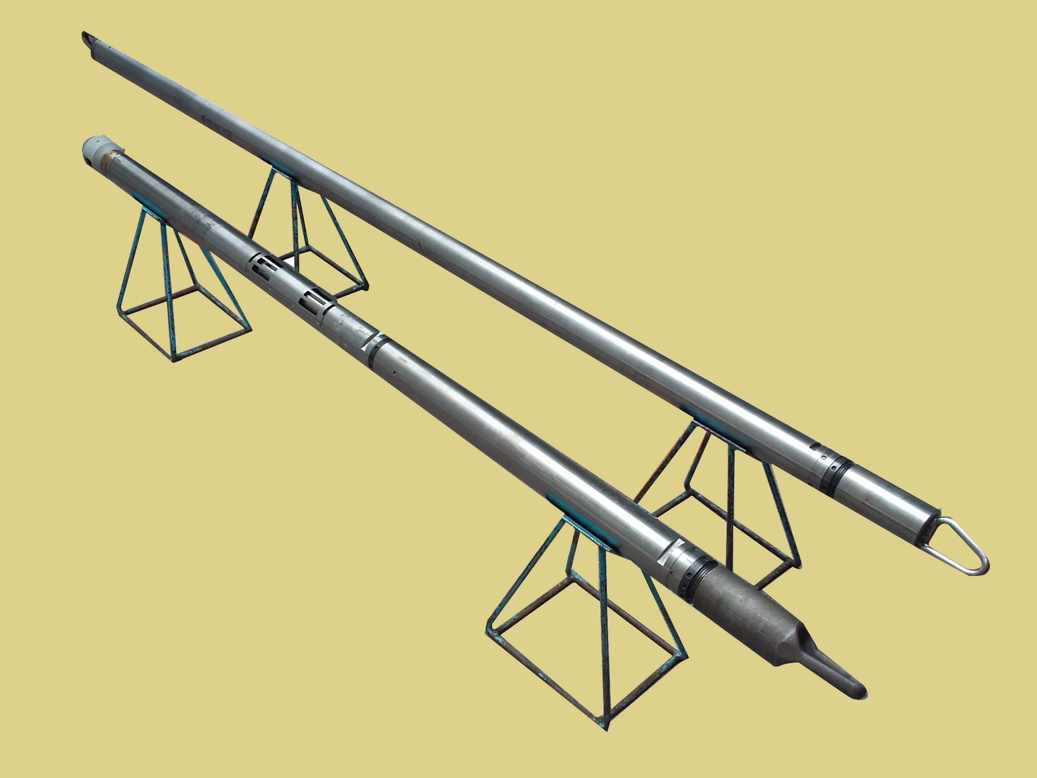
UBIT is a kind of ultrasonic logging tool. It can be used in the well full of liquid, but it is cannot be used in the mud full of gas (The data will weaken seriously). It has two kinds of logging services: IMAGED MODE and CASED HOLE MODE.
|
INTRODUCTIONCOMPOSITIONTECHNICAL SPECIFICATIONS
UBIT is a kind of ultrasonic
logging tool. It can be used in the well full of liquid, but it is cannot be
used in the mud full of gas (The data will weaken seriously). It has two kinds
of logging services: IMAGED MODE andCASED HOLE MODE. IMAGED MODE is used for
the imaging in the open hole, cased hole and the formation crack investigation.
The CASED HOLE MODE is used to evaluate the cement sonic impedance outside case
and check the corrosion of case.
UBIT tool is composed of the electric circuit, directional sub and rotating sonde.
The electric circuit is composed of RTU board, V40 processor board, DSP signal
processing board, transmitting control and preamplifier board and motor control
board and slow A/D board. The RTU address is 2C0 0.The surface logging system
communicates with CAST by D4TG to get the useful downhole information.
UBIT includes two ultrasonic transducers, each
of which can act as either transmitter or receiver. The imaging transducer is
mounted on the rotating scanner head. When the ultrasonic transducer of 360
degree rotation transmits the sonic wave beam to side wall, the sonic energy is
transmitted by the side wall, and return to the transducer. Recode the returned
sonic energy (amplitude) and transmitting time through the transducer. The
returned sonic energy is mainly related with the sonic resistance of side wall
and the geometry shape of borehole. In the well wall without the crack, the
greater the sonic resistance of well wall is, the bigger the returned energy is,
Wise versa, In the well wall of the crack hole, the returned sonic energy is in
proportional to the area of out zone of
the hole. In addition, the smoothness of well wall influences the returned
sonic energy. If the well wall is not flat, it will scatter to the sonic, and the
returned the sonic energy will become small. The other transducer is the mud transducer
(Mud -Cell Transducer). It is used to measure the sonic velocity of borehole
fluid. The mud transducer is opposed to the fix reflector, because the distance
of reflector and transducer is known, so by recording the transmitting time of transducer,
slowness of borehole fluid can be confirmed.
The main influence factors of ultrasonic imaging: Shape of
transducer, work frequency, distance to the formation, the mud density in the
well, borehole and the centered condition of the tool. The smaller of
transducer’s shape is, the higher work frequency is, it is more near to the
formation, the mud density is small, and the facula is small, then the attenuation
of sonic wave is small. While the more small of the transducer is, the power is
small; the work frequency is higher, the
sonic attenuation is big; the mud density is bigger, the sonic attenuation is
bigger. If decrease the work frequency, it influences the space resolution. If
the well is not regular or the centralizing of tool is not good, the image
appears the vertical stripe to cover the character.
Max. Temperature: 175℃
Max. Pressure: 140Mpa
O.D:
92mm
Length:
5450mm
AC power supply: 120Vac±10v,50~60HZ
DC power : 150VDC,1.5A
Caliper Measuring range:
5.5’’~13.375’’(cased
hole)
4.5’’~12.5’’ (Open hole)
Parameter Comparison of Imaging Mode and Casing Mode
|
|
Imaging mode
|
Casing mode
|
|
Type of transducer
|
Ultrasonic
transducer
|
Ultrasonic transducer
|
|
Transmitting velocity
|
200 times /turn
|
100 times/ turn
|
|
Vertical scanning rate
|
40 turn/foot
|
4turn/foot
|
|
Complitable system
|
DITS System
|
DITS System
|
|
Principle
|
Ultrasonic transmit principle
|
Ultrasonic transmit principle
|
|
Sample angle
|
1.8℃
|
3.6℃
|
|
Vertical sample
|
0.2in
|
6.0,3.0,1.0in
|
|
Logging velocity
|
21ft/min
|
60,30,10ft/min
|
|
Main curve
|
reflection amplitude and time imaging picture
|
reflection amplitude imaging, radius imaging, sonic
impedance imaging, casing thickness imaging
|
|
Auxiliary curve
|
Radius curve,azimuth,Relative azimuth,well deviation,sound of velocity of sound
|
Well deviation,Relative azimuth,fluid sound velocity,Mud sonic resistance
|
|
Min.open hole
|
4.5in
|
5.5in
|
|
Max. hole
|
12.5in
|
13.375in
|