Product Name:WDSC MICRO-RESISTIVITY SCANNING IMAGING LOGGING TOOL
|
Type:
|
WDSC
|
|
producer:
|
Huanding Energy Services
|
|
Description:
|
In nowaday’s oil exploration field, thorough and effective reservoir evaluation is more important than ever before. The extended Micro-Resistivity Scanning Imaging Logging Tool (WDSC) is a new tool designed to provide a clear and image of stratum around borehole .
|
INTRODUCTIONWORKING RPINCIPLECHARACTERISTICSSPECIFICATIONSAPPLICATION
In nowaday’s oil exploration
field, thorough and effective reservoir evaluation is more important than ever
before. The extended Micro-Resistivity Scanning Imaging Logging Tool (WDSC) is
a new tool designed toprovide
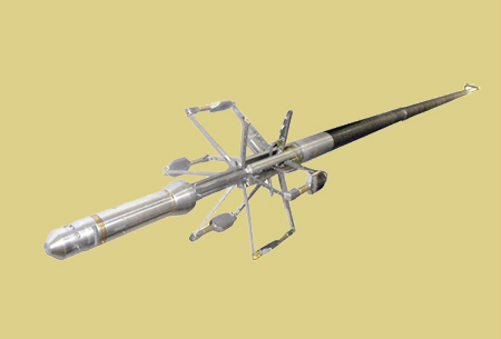
a clear and image of formation around borehole .Based on the Six-Arm Dipmeter technology, the 6 pads of WDSC are each mounted
on an independent arm (6 in all), allowing improved electrode-to-formation
contact. High quality formation resistivity data are achieved by using 150
pad-mounted button electrodes distributed at 25 per pad. This finally produces
tool location data, six micro-resistivity curves and six independent caliper
curves with a measurement resolution of 0.2 inch.
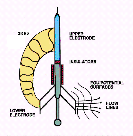
WDSC is a non-focus electric logging tool. The tool
current loop goes from lower button electrode on pad into formation, then comes
back to upper electrode. In fact, the housing of cartridge acts as upper
electrode.In the logging process, the pads are forced to contact against the
borehole wall by the motor-drive mechanical push-and-pull system. Then the logging
software controls emitting current upon measured value, and the current and
potential difference measurements on each button electrode meanwhile are
recorded, presenting the micro-resistivity variation within the formation
around the borehole.
The
tool resolution is closely related to the pad-mounted button electrodes
arrangement. WDSC applies such a array shown in the following diagram, by which
0.2 in. (5mm) of both the all-around resolution and vertical resolution and 80%
coverage of a 6.5 in hole size can be achieved when the tool works at the
maximum investigation speed of 1800ft/h.

WDSC
takes the advanced design concept of digitalized pad so as to greatly enhance
the image quality and the measurement range. With the sample signals
digitalized in the pad, the button electrode enables serial digital
communication with electric circuit. As a result, the coupling jam among signal
lines is reduced and the signal to noise ratio is improved, which is beneficial
for minor signal acquisition.

|
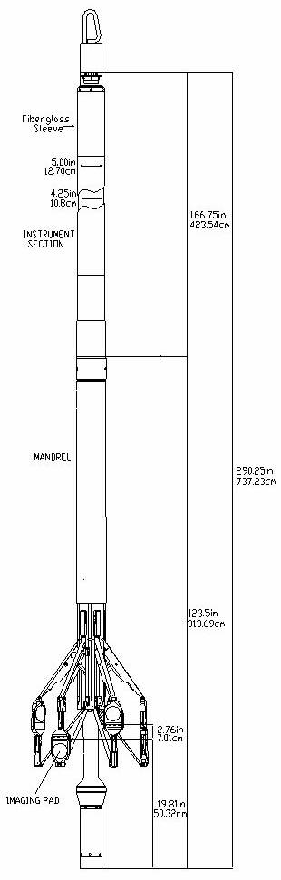
DIMENTIONS AND RATINGS
|
|
Max temp: 175℃
|
Max pressure: 140Mp
|
|
Max OD: 5 in(12.7cm)
|
Min Hole: 6.25 in(15.875cm)
|
|
Length: 24.18 ft(7.37m)
|
Max Hole: 21 in(53.34cm)
|
|
|
Weight: 496 lb(225kg)
|
|
BOREHOLE CONDITIONS
|
|
Borehole Fluids:Salt
Mud ■ Fresh Mud■ Oil □
Air □
|
|
Recommended
Logging Speed(High Data Rate):30ft/min(9.1m/min)
Recommended
Logging Speed(Low Data Rate):20ft/min(6.1m/min)
|
|
HARDWARE CHARACTERISTCS
|
|
Source Type: Induced Current
|
|
Sensor Type: Micro-resistivity Buttons
|
|
Sensor arrangement: 2 rows containing 12&13 sensors,
respectively
0.3 in. between rows
0.2 in. between sensors
on each row
0.1 in. between sensors
when both rows are superimposed
|
|
Sampling Rate: 120 samples/ft(394 samples/m)
20ft/min(Low Data Rate)&
30ft/min(High Data Rate)
|
|
Combinability: DITS Compatible, Bottom Only
310 Words/Frame(Low Data Rate)
456 Words/Frame(High Data Rate)
|
|
MEASUREMENT
|
|
|
Resistivity
|
Azimuth
|
Rotation
|
Deviation
|
Caliper
|
|
Principle
|
Micro-Resistivity
|
Navigation
|
6 arm.
|
|
Range
|
0.2-10,000ohm-m
0<Rt/Rm<20,000
|
0-360°
|
0-360°
|
0-90°
|
6-21in
|
|
Vertical
Resolution 90%
|
0.2in
|
N/A
|
N/A
|
N/A
|
N/A
|
|
Depth of
Investigation
|
Formation
Dependent within 12in.
|
N/A
|
N/A
|
N/A
|
N/A
|
|
Sensitivity
|
N/A
|
0.1°
|
0.1°
|
0.03°
|
0.1in
|
|
Accuracy
|
N/A
|
±5°
|
±2°
|
±0.6°
|
±0.1in
|
|
Primary
Curves
|
Image
|
AZI, HAZI
|
ROT
|
DEVI
|
CAL 1-6
|
|
Auxiliary
Curves
|
Micro-Resistivity, Dip Angle, Dip AZI,
Borehole Inclination
|
|
CALIBRATION
|
|
Primary:Resistivity
box, navigation cal stand & vertical hoist, 7-15 in. caliper rings
Wellsite:Resistivity
box, operational check of navigation sensors, 7 in. caliper rings
|
|
PHYSICAL STRENGHTS
|
|
Item
|
Tension
|
Compression
|
Torque
|
|
Tool Joints
|
130,000 lbs
|
130,000 lbs
|
600 lb-ft
|
|
Mandrel Body
|
130,000 lbs
|
130,000 lbs
|
600 lb-ft
|
|
4 1/4-inch Isolator
|
130,000 lbs
|
130,000 lbs
|
600 lb-ft
|
|
|
|
|
|
|
|
|
|
|
|
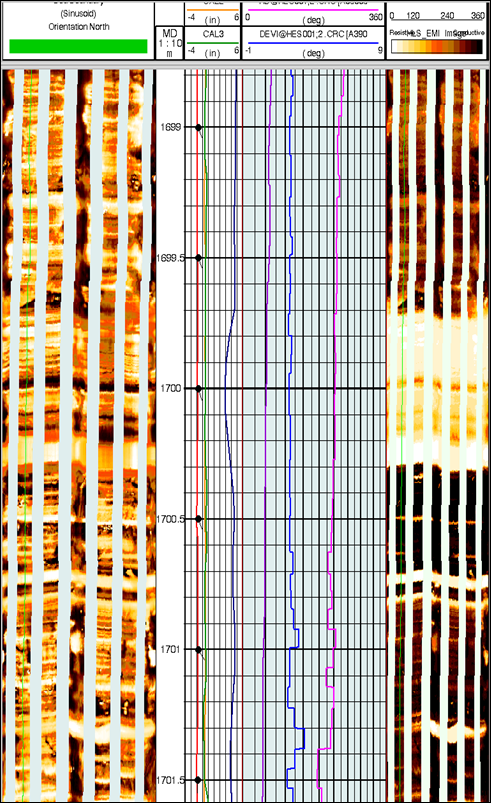
The real-time image
data produced at the wellsite will go through a series of post-processing and
image enhancement. The micro-resistivity image represents the borehole wall
formation resistivity hetero-feature changes, in which the change of
resistivity reflects variation of the lithology, porosity and mud content. The
fluid nature in the alluvion and the irregular borehole wall will have certain
impact on the image.
Application of MRIT
images in geological analysis mainly includes the following.
?Fracture
identification and evaluation
?Thin
bed evaluation
?Detailed
stratigraphic and sedimentological analysis
?Secondary
porosity analysis and geological structure interpretation
?Core
restoring and lithology characterization assistance
The figure below
shows MRIT images after post-processing wellsite raw data, in which the
fracture bisecting the borehole along a north to south trend and the sand-shale
boundary is clearly seen.